The question of how a charging process can be optimally controlled is central to the charging infrastructure of electric vehicles. The “control and monitoring” functional unit is one of several functional units of a charging station. This is where information is collected, processed and the charging process is controlled. Data is exchanged between the charging station, vehicle, users and other systems.
Despite identical functional requirements, a distinction is made between AC and DC charging in order to meet the respective technical requirements.
Efficient control of AC charging via PWM and intelligent load management
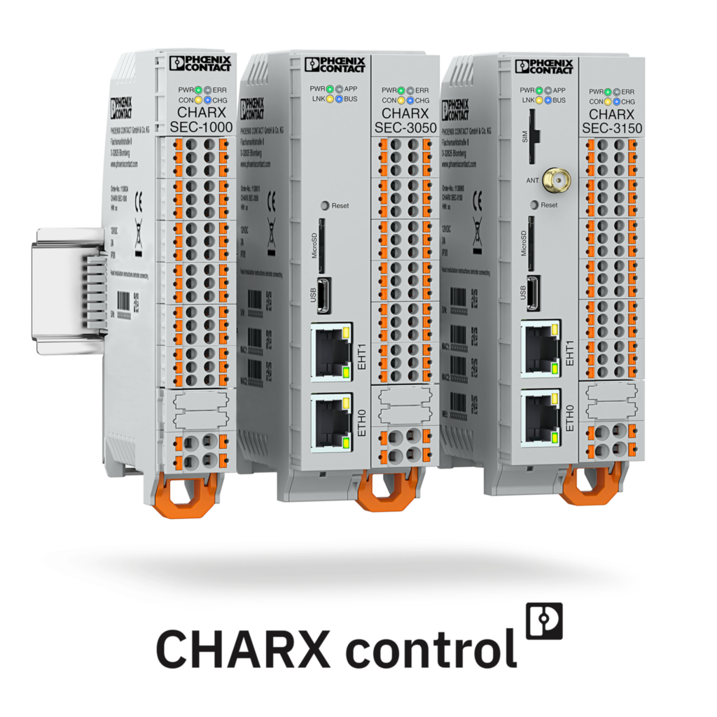
In AC charging, the AC charging controller takes over communication with the electric vehicle and thus forms the central communication point, the heart and brain of the charging station. This is where charging processes are enabled, started, controlled and stopped in conjunction with the vehicles.
Communication with the vehicle takes place via pulse width modulation (PWM), which runs via the CP (Control Pilot) signal contact integrated in the charging connector or charging cable. The charging controller and vehicle exchange information via the PWM signal: On the one hand, about how much charging current and voltage the charging station can supply and, on the other, about the maximum current and voltage the car can absorb. By exchanging these parameters, both sides “agree” on the charging current that is allowed to flow. This process is therefore also known as a handshake. Once all the parameters have been negotiated, the charging controller gives the power contactor the command to switch the current to the line.
In addition to this basic function, charging controllers can perform other additional functions that contribute to optimal control of the charging process.
Intelligent load management for multiple charging points
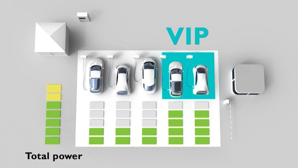
Smart load management is an important aspect, especially for charging parks where several charging points share a grid connection. In the simplest case, the available charging power is configured in the web interface of the charging controller and then distributed evenly to all charging points to protect the grid connection from overloading and the distribution grid from unbalanced loads.
Instead of equal distribution, certain charging points can also be prioritized higher or lower. This can be useful for short-stay parkers or VIP guests, for example, or if customers in a public HPC charging park pay a correspondingly higher price per kilowatt hour (kWh) for a higher charging power.
If there are other consumers in addition to the charging stations, e.g. in or on the adjacent building, or if there are generators such as a photovoltaic system or a combined heat and power plant (CHP), a building or energy management system is usually used that monitors all energy flows, forecasts generation and demand and calculates how much energy is available for the charging points at the current time. It communicates this fluctuating value to the charging controller via a Modbus/TCP signal. This is also known as dynamic current value specification or dynamic load management.
Optional network connection and communication protocols for AC charging controllers
AC charging controllers are available on the market in different variants and can therefore be tailored exactly to the target application. The controllers can be used in a simple version as a stand-alone controller for charging points without a network connection.
With the appropriate equipment variant of a charging controller, network connections can be established, e.g. via LAN, WLAN or cellular communication. Supported and common communication protocols include OCPP for communication with the backend system for billing, Modbus/TCP for dynamic current value specification by the building management system and ISO 15118 for extended functions such as plug-and-charge (PnC) or bidirectional charging in the form of vehicle-to-grid (V2G) or vehicle-to-home (V2H). However, as such network connections can also be potential gateways for hackers and cybercriminals, the cybersecurity of charging controllers should be kept up to date with regular software updates.
Server-client structures for scalable AC charging stations
By combining several AC charging controllers into a server-client network, it is possible to set up charging stations with several charging points, so-called double or triple chargers. In this case, there is always a server controller within the charging station that handles communication with the outside world and, depending on the number of charging points, one or more client controllers that behave according to the specifications of the server controller and do not have a network connection themselves.
A server-client network can also be used to implement a charging point architecture with a central technology cabinet on the one hand and many small decentralized charging points, so-called dispensers or satellites, on the other, as is common in multi-storey parking lots or parking lots. While all electronics such as charging controllers and energy meters are located in the technology cabinet or technology room, the dispensers or satellites are reduced to a housing, charging connection (charging cable or charging socket) and, if necessary, an RFID reader. This means that these charging points can be designed very compactly and damage is less severe in the event of vandalism.
Safety functions for AC charging: Residual current and temperature measurement
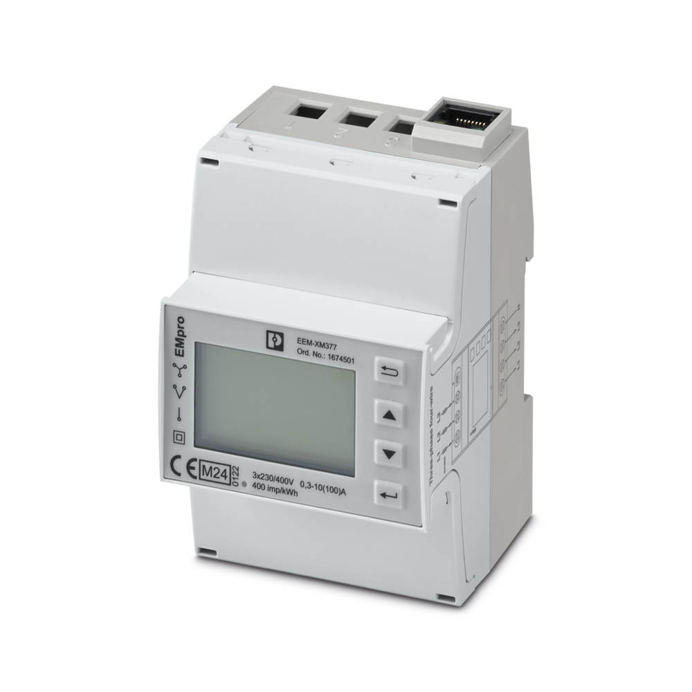
An optional AC energy meter can be connected to an AC charging controller. This is necessary if charging processes are to be billed or load management is to take place. Energy measurement is always recommended as a source of information for optimizing consumption. The measured energy values can also be used to implement safety measures. For example, the AC charging controller can switch off the charging process in the event of overcurrent.
In order to be allowed to bill charging processes at commercial or public charging points, certain requirements must also be met with the aim of ensuring tamper-proofing and transparency for the end customer. On the one hand, the energy meter must be certified in accordance with the applicable national standards and laws, e.g. the European MID (Measuring Instruments Directive), or it must comply with calibration law, i.e. the German Measurement and Calibration Act. On the other hand, the complete charging station must be approved and certified as an integrated charging system by a conformity assessment body such as the VDE Institute prior to commissioning. This currently only applies in Germany, but in other countries such as France, Italy and Spain, similar regulations are in preparation or have already been implemented in some cases.
Residual current and temperature measurement as safety features for AC charging
Residual current measurement is a safety feature that is required by law in AC charging stations in many countries. It detects AC and DC currents that cannot flow from the car back into the grid due to poor insulation, for example. The measurement can be carried out via a type B protective circuit breaker, which detects both AC and DC residual currents. A much cheaper alternative is a type A circuit breaker. As this only detects AC residual currents, it must be combined with a DC residual current measurement.
Integration of the residual current modules
DC residual current monitoring modules can be connected and configured directly to the AC charging controller. The charging cable wires are routed through the monitoring module’s toroidal coil for measurement. This safety feature can be easily implemented thanks to the overhead cabling.
Integration of temperature measurement
Temperature measurement at the power contacts is not a standard requirement for AC charging. However, it can be useful in order to detect overheating during the charging process at an early stage and thus further increase safety. Overheating can be caused, for example, by increased ambient temperatures, intense sunlight, soiling of the power contacts or high loads on the charging technology.
Temperature sensors are already integrated in some AC charging cables and AC charging sockets, usually in the form of a chain of PTC sensors. With AC charging sockets, it can also be retrofitted if required. The sensor cables are connected to an input of the AC charging controller so that the additional installation effort is minimal.
Safe and precise control of DC charging: energy meters, insulation monitoring and temperature measurement
In principle, the DC charging controller performs the same functions as the AC controller, but is designed for DC currents. It actively communicates with the power electronics in order to charge electric vehicles quickly, safely and efficiently.
Via its CAN bus interface, the DC charging controller provides the power electronics with important charging parameters such as current and voltage. It also receives temperature values or fault messages from the power electronics in order to adapt the charging process accordingly.
DC energy measurement for exact billing and load management
With fast charging, various pieces of information are required for both load management and billing. Theoretically, AC-side energy measurement would be conceivable. However, due to power dissipation in the AC-DC conversion, the billing would be based on distorted DC values. For this reason, regional standards and laws often stipulate a DC-side energy meter per charging point to ensure precise measurement. In addition, some countries have the same MID and calibration law requirements as for AC charging.
Temperature measurement at high DC currents for safety
In DC charging, temperature measurement at power contacts of the DC charging cables is required by standards and is therefore always permanently integrated in order to monitor the temperature development over the entire distance to the vehicle and to ensure safety at the usually high DC currents of several hundred amperes. Depending on the equipment of the charging station, the charging process is either stopped, the charging current is reduced (derating) or the cooling capacity for the charging cable is increased when the limit temperature is reached.
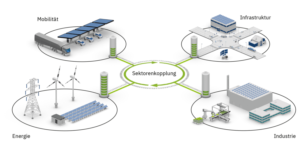
Sector coupling in charging infrastructure: intelligently networking energy
Sector coupling is an important aspect of charging infrastructure. It describes the intelligent networking between buildings, charging infrastructure operators, energy producers and grids as well as charging stations and electric vehicles. Sector coupling is the prerequisite for optimal energy use and CO2-neutral mobility in the All Electric Society. A world in which energy from renewable sources is used efficiently and affordably.
The charging controller plays a central role here, as it must support various communication protocols to enable integration into complex energy systems. Sector coupling offers enormous potential for increasing efficiency and reducing
Conclusion: Intelligent control of AC and DC charging processes
Optimum control of the charging process is essential for the efficiency and safety of the charging infrastructure. Both AC and DC charging controllers offer extensive functions and safety features that optimally control and monitor the charging process. The integration of load management and sector coupling also contributes to efficient energy use and CO2-neutral mobility.
Video tutorial: How do I optimally control the charging process for electric vehicles?
FAQ
Frequently asked questions
What are the benefits of a load management system for charging infrastructure?
Intelligent control of the charging process ensures efficient use of the charging infrastructure and prevents peak loads in the power grid. This helps operators reduce costs and improve grid stability. For EV drivers, it means shorter charging times and a more sustainable energy supply.
How does dynamic control of the charging process work?
A load management system optimally distributes the available energy across all connected vehicles. This prevents overloads, reduces operating costs, and ensures that charging points remain reliable even during high demand. For fleet operators, this is crucial to keep all vehicles ready for use on time.
What role does communication between the vehicle and the charging point play?
Dynamic control adjusts the charging power in real time based on the current grid situation. The system considers factors such as electricity tariffs, available energy, and vehicle priorities. This not only increases efficiency but also supports the integration of renewable energy sources.
What role does communication between the vehicle and the charging point play?
Communication via standards such as ISO 15118 enables intelligent coordination between the vehicle and the charging point. This allows features like Plug & Charge and automatic adjustment of charging power—providing greater convenience and safety during charging.
How can companies future-proof their charging infrastructure?
Companies should invest in scalable systems that integrate load management, dynamic control, and interfaces for energy management. This ensures flexibility and allows the charging infrastructure to expand easily as the number of electric vehicles grows.
Discover suitable products now
Here you will find a selection of relevant products – based on the topics and recommendations from our blog post.
